In recent years, metal brake bending machines have been widely used in various industries, and the processing range of bending machines has been expanding. However, there has not been a systematic discussion on the calculation of bending force. At present, there are roughly two types of bending force calculation formulas recommended in the manuals of various press brake bending machine manufacturers.
![]()
P - bending force, KN;
S - sheet thickness, mm;
l - the bending length of the sheet, m;
V - the width of the lower die opening, mm;
σb - Material tensile strength, MPa.
The bending force parameter table recommended by the manufacturer is also calculated according to the above formula.
The derivation process and application scope of bending force calculation formula
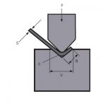
Figure 1 is a schematic diagram of the work during sheet bending. The following describes the derivation process of the bending force calculation formula and two additional parameter conditions. First, there are such recommendations in the product manual. In free bending, the selected lower die opening width V is 8 to 10 times the sheet thickness S. Here we take the aspect ratio .
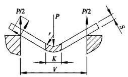
Figure 1 Schematic diagram of bending
P - bending force
S - sheet thickness
V - lower die opening width
r - the inner radius when the sheet is bent
K - the width of the horizontal projection of the bending deformation zone![]() =9
=9
Second, the manufacturer lists the corresponding values of the die width V and the inner diameter r of the bending workpiece on the bending force parameter table. Generally r=(0.16~0.17)V. Here, the diameter-to-width ratio ![]() =0.16.
=0.16.
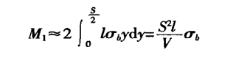
During the bending process of the sheet metal, the material in the deformation zone is in a highly plastic deformation state, and it is bent at an angle around the centerline. On the outer surface of the bending zone, micro-cracks may appear in some cases. On the cross-section of the deformation zone, except for the vicinity of the central layer, the stresses at other points are close to the tensile strength of the material. The upper part of the neutral layer is compressed and the lower part is tensioned. Figure 2 shows a cross-section and corresponding stress diagram in the deformation zone.
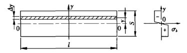
Figure 2 Stress diagram
S - sheet thickness
l - sheet bending length
The bending moment on the cross-section of the deformation zone is:
The bending moment generated by the bending force of the machine in the deformation zone is (see Figure 1):
![]()
From![]()
![]()
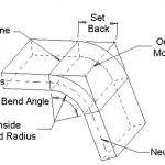
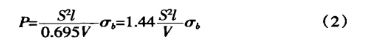
When using general-purpose molds for free bending on a bending machine, most of the sheet metal is bent 90°. As shown in Figure 3. K is:
![]()
Substituting K into equation (1), we get:
The tensile strength of ordinary materials σb=450N/mm2, substituting formula (2) into:
![]()
It can be seen from the derivation process that when using equation (2) or equation (3) to calculate the bending force, the two additional
parameter conditions mentioned above need to be met. That is, the aspect ratio![]() =9, the diameter-to-width ratio
=9, the diameter-to-width ratio![]() =0.16, otherwise it will cause a big error.
=0.16, otherwise it will cause a big error.
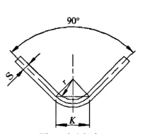
Figure 3 Free bending
S - sheet thickness
r - the inner radius when the sheet is bent
K - the width of the horizontal projection of the bending deformation zone
New methods and steps for calculating bending force
Due to design or process requirements, it is sometimes difficult to meet the above two additional requirements at the same time. At this time, the recommended calculation formula should not be used to calculate the bending force but should be carried out according to the following steps.
(1) According to the plate thickness S, the bending radius r, and the lower die opening V, the width to thickness ratio and the diameter to width ratio are respectively calculated.
(2) Calculate the projection width of the deformation zone according to the deformation of the sheet.
(3) Apply formula (1) to calculate the bending force.
In the calculation process, the difference of the bending radius and the change of the corresponding deformation zone have been considered. The bending force calculated from this is more accurate and reliable than the result calculated by the usually recommended formula. Now give an example to illustrate, as shown in Figure 4.
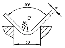
Figure 4 New calculation method
Known: The sheet thickness S=6mm, the sheet length l=4m, the bending radius r=16mm, the lower die opening width V=50mm, and the material tensile strength σb=450N/mm2. Find the bending force required for free bending.
First, find the aspect ratio and diameter-to-width ratio:
![]()
Secondly, calculate the projection width of the deformation zone:
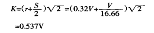
Finally, use equation (1) to find the bending force:
![]()
If the usual recommended formula is used to calculate the bending force:
![]()
From ![]() = 1.5, it can be seen that the difference between the two is 1.5 times. The reason for this error is that the bending radius in this example is relatively large, and the corresponding deformation area is increased, so a greater bending force is required during bending. In this example, the diameter-to-width ratio=0.32, which has exceeded the additional conditions of the parameters introduced above. It is obviously inappropriate to use the usually recommended formula to calculate the bending force. You can see the advantages of the new calculation method from this example.
= 1.5, it can be seen that the difference between the two is 1.5 times. The reason for this error is that the bending radius in this example is relatively large, and the corresponding deformation area is increased, so a greater bending force is required during bending. In this example, the diameter-to-width ratio=0.32, which has exceeded the additional conditions of the parameters introduced above. It is obviously inappropriate to use the usually recommended formula to calculate the bending force. You can see the advantages of the new calculation method from this example.
Conclusion
The steps and formulas for calculating the bending force introduced here are not only applicable to the angle bending of sheet metal but also applicable to the arc bending (strictly speaking, it should be called the angle bending with an extra-large bending radius). It should be pointed out that the shape of the mold is special when the sheet is bent into an arc shape. When calculating the projection of the deformation zone, it must be calculated according to the technological parameters set in the technological process, which cannot be expressed by a simple formula.
When designing an arc-shaped mold, using the method introduced in this article to calculate the bending force, satisfactory results can be obtained.
اړوند محصولات
 د پریس بریک بیلینګ ماشین مناسب ډای څنګه غوره کړئ
- د هیدرولیک پریس بریک ماشین ټونج څنګه غوره کړئ
- ولې د پریس بریک بینډنګ ماشین ته د خسارې سیسټم اضافه کړئ
- WILA د متوسط او ضخامت پلیټونو د مینځلو مؤثر حل
- د CNC د مینځلو ماشین مهارتونه وکاروئ
- د مخکښو صنعتونو کې د راتلونکي نفوذ وړتیا لپاره د فایبر لیزرونو ګټې
- د دودیز خړوبولو ترتیب او د موډل ماشین مولډ ورځني کارونې مشخصات
- د کانتون میله
- د پریس بریک تاج کول څه شی دی؟
- ستاسو د پریس بریک لپاره د بینډ الاؤنس محاسبه کولو څرنګوالی