You have your Press Brake, set up to bend your material exactly where you want it, at the exact angle that the job requires. Your forming is on-form, your numbers have been crunched and your trusty Press Brake is just waiting to do its thing.
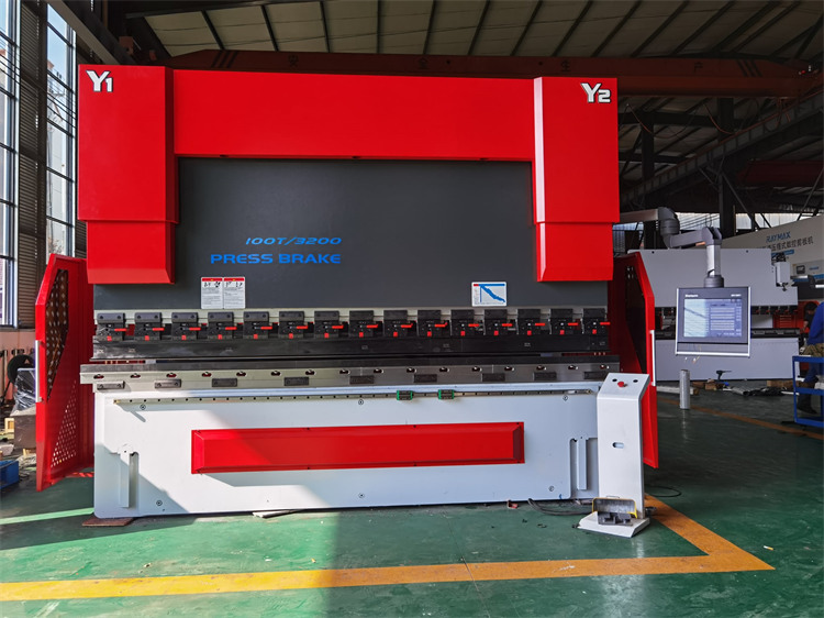
But there is one vital thing that is easily overlooked and understanding how it works and more importantly how to set it up is vital. We are of course talking about the process of crowning.
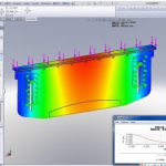
Crowning comes in to play whenever long or large parts are bent, it can also be beneficial on longer, heavier Press Brakes and those at the top end of the power scale. When load is applied to form a bend, a degree of deflection occurs. This causes deformation and that means that if your bend is spot-on accurate at the ends, thanks to the servo-hydraulic system and pistons at the ends of the beam, it might not always be the case nearer to the centre of your workpiece.
That isn’t a case of operator error or an issue with your Press Brake; it is more a simple fact of material science and physics. The process of compensating for that phenomenon is, in a nutshell crowning.
To ensure a consistent bend along the full length of a workpiece a crowning system is crucial, it can either be in the Press Brake’s beam, in the table itself or even both. It ensures the angles in the centre of your beam match those at the ends, compensating against that deflection exactly where compensation is needed. Hydraulic crowning tends to be built in to today’s Press Brakes; there are also CNC wedge style systems that might be offered as an add-on by the tooling supplier or Press Brake manufacturer.
1. Hydraulic crowing
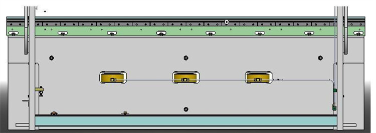
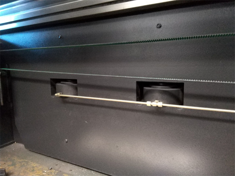
On the press brake frame, in addition, to installing two hydraulic cylinders at two sides, install another two-auxiliary hydraulic cylinder in the middle of the machine. When stroke down, the auxiliary cylinder filed with liquid oil and go downward. During bending process, hydraulic oil inlet into the auxiliary cylinder, so that the slider generate downward deflection for compensation.
Install the auxiliary hydraulic cylinder in the lower part of the worktable. During bending process it generates an upward force on the worktable, which forms the automatic crowning system.
The pressure compensation device is composed of several small oil cylinders. comprising an oil cylinder, a motherboard, an auxiliary plate and a pin shaft and a compensating cylinder is placed on the worktable, and a pressure compensation system is formed with a proportional relief valve.
When working. the auxiliary plate supports the oil cylinder, the oil cylinder holds up the motherboard up. just overcomes the deformation of the slider and the worktable. The convex device is controlled by a numerical control system, so that the preload can be determined according to the thickness of the plate, the opening of the die and the tensile strength of the material when bending different sheet materials.
The advantage of hydraulic crowning is that it can realize the deflection compensation for continuous variable deformation with large compensation flexibility, but there are some disadvantages of complex structure and relatively high cost.
2. Mechanical crowning
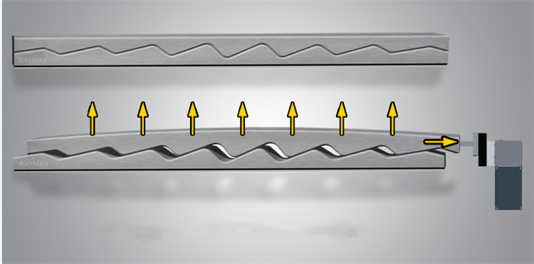
Mechanical crowning is a kind of new deflection compensation method, which is generally used triangular oblique wedge structure.
The principle is that the two-triangle wedge block with a angles, the upper wedge moving i fixed at x-direction.can only move in y-direction. When the wedge moves the distance along the x-direction, the upper wedge moves up the h distance under the lower wedge force. which is the principle of the mechanical crowning.
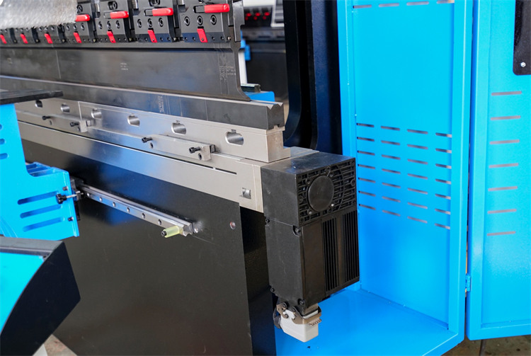
Regarding existing mechanical compensation structure. two bolster plates are placed in full length on the worktable, the upper and lower plates are connected through the disc spring and bots. The upper and lower plates are consist of a number of oblique wedges with different slopes, through the motor drive to make them relatively moving, forming and ideal curve for a set of convex position.
